How to Make Sure Every Inch Gets the Right UV Dose: A Comprehensive Guide to UV Uniformity
In the world of industrial manufacturing, precision is the difference between a high-quality product and a costly batch of scrap. Whether you are curing high-tech adhesives in electronics, applying protective coatings to automotive parts, or disinfecting medical instruments, the concept of “UV dose” is central to your success. However, achieving the correct dose in a laboratory setting is one thing; ensuring that every square inch of a complex, three-dimensional part receives that exact dose in a high-speed production environment is quite another.
Inconsistent UV exposure leads to a host of problems: tacky surfaces, delamination, poor chemical resistance, and incomplete sterilization. To prevent these issues, manufacturers must move beyond guesswork and implement rigorous process controls. This guide will explore the technical nuances of UV distribution, the physics of light delivery, and the practical steps you can take to ensure total uniformity across every inch of your substrate.
Understanding the Components of UV Exposure
Before we can optimize for uniformity, we must understand exactly what we are measuring. In UV processing, two primary metrics define the “dose” delivered to a surface: Irradiance and Energy Density.
Irradiance (The Intensity)
Irradiance is the “brightness” or intensity of the UV light hitting a surface at any given moment. It is measured in Watts per square centimeter (W/cm²) or milliwatts per square centimeter (mW/cm²). High irradiance is often necessary to initiate the chemical reaction in UV-curable materials, especially in thick coatings where the light must penetrate deep into the layer.
Energy Density (The Dose)
Energy Density, often simply called the “dose,” is the total amount of UV energy delivered to the surface over a period of time. It is the mathematical integral of irradiance over time, measured in Joules per square centimeter (J/cm²) or millijoules per square centimeter (mJ/cm²). Think of irradiance as the speed of a car and energy density as the total distance traveled. To ensure a proper cure, you need both the right speed (to kickstart the reaction) and the right distance (to complete it).
When we talk about “making sure every inch gets the right UV dose,” we are talking about maintaining a consistent energy density across the entire geometry of the part, regardless of its shape or orientation.
The Challenges of Achieving Uniformity
In a perfect world, every UV lamp would emit a perfectly uniform curtain of light, and every substrate would be a flat, two-dimensional plane. In reality, several factors work against uniformity:
- The Inverse Square Law: The intensity of light decreases significantly as the distance between the source and the substrate increases. If one part of your product is 2 centimeters closer to the lamp than another, it will receive a much higher irradiance.
- Shadowing: Three-dimensional objects often have “nooks and crannies” or protruding features that block light from reaching recessed areas. These shadows are the primary cause of localized cure failure.
- Lamp Aging: UV lamps (both Mercury vapor and LED) degrade over time. However, they don’t always degrade uniformly. A bulb might become dimmer at the ends than in the center, leading to “hot spots” and “cold spots” across the conveyor.
- Reflector Degradation: In traditional microwave or arc lamp systems, reflectors are responsible for directing up to 70% of the UV energy. If reflectors are warped, dusty, or oxidized, the light distribution will become unpredictable.
- Angular Dependence: The angle at which light hits the surface (the angle of incidence) affects how much energy is absorbed versus reflected. Surfaces tilted away from the light source receive a lower effective dose.
Strategies for Ensuring Uniform UV Coverage
To ensure every inch of your product is properly treated, you need a multi-faceted approach that addresses hardware configuration, process mapping, and ongoing monitoring.
1. Optimize Lamp Geometry and Orientation
For flat substrates, lamps are typically oriented perpendicular to the direction of travel. However, for 3D parts, you may need a “multi-axis” lamp arrangement. This involves placing lamps at various angles (side-firing, top-down, and even bottom-up) to ensure that light reaches all faces of the object.
Using staggered lamp arrays can also help. By overlapping the footprints of multiple lamps, you can smooth out the “valleys” in intensity that occur at the edges of a single lamp’s output profile.
2. Selecting the Right Reflector Shape
Reflectors are not just “mirrors”; they are precision optical components. There are two main types used in UV curing:
- Elliptical Reflectors: These focus the UV light into a tight, high-intensity line (focal point). This is ideal for high-speed applications where you need maximum irradiance in a small area.
- Parabolic Reflectors: These create a collimated, “flood” beam of light. While the peak irradiance is lower, the light is more evenly distributed over a larger area, which can be beneficial for parts with slight height variations.
3. Implementing UV LED Technology
UV LEDs offer significant advantages for uniformity. Unlike traditional bulbs, which are single points or tubes of light, LED systems are comprised of arrays of hundreds of small diodes. These arrays can be engineered to provide an incredibly uniform output across the entire width of the curing window. Furthermore, LEDs do not require reflectors to the same extent as mercury lamps, reducing the variables that can lead to non-uniformity.
Measurement: The Key to Process Control
You cannot manage what you do not measure. To ensure every inch is getting the right dose, you must perform regular UV mapping of your production line.
Using UV Radiometers
A UV radiometer is a calibrated instrument designed to measure the irradiance and energy density within specific spectral bands (UVA, UVB, UVC, or UVV). To check for uniformity, you should not just measure the center of your conveyor. Instead, perform a “cross-web” profile by placing the radiometer at the left, center, and right positions of the belt.
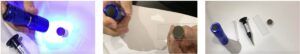
The Role of UV Strips and Labels
For complex 3D parts where a bulky radiometer cannot fit, UV-sensitive strips or “dots” are invaluable. These color-changing labels can be adhered to the recessed areas, underside, or vertical walls of a part. After passing through the UV system, the color change is compared against a reference chart to estimate the dose received in those hard-to-reach spots.
Mapping the Cure Profile
A “cure profile” is a visual representation of how UV energy is distributed across your part. By using a combination of radiometers and UV strips, you can create a map that identifies “cold spots.” Once these spots are identified, you can adjust lamp height, angle, or conveyor speed to compensate.
The Impact of Conveyor Speed on Dose Uniformity
Conveyor speed is the primary variable used to control energy density (mJ/cm²). While it doesn’t change the irradiance (the brightness of the lamp), it changes the “dwell time”—the amount of time the part spends under the light.
If your conveyor speed is inconsistent, your dose will be inconsistent. Precision motor controllers and regular calibration of the conveyor tachometer are essential. Furthermore, if you are curing parts that are tall, the top of the part is moving through a higher-intensity zone than the base. You must calculate your speed based on the “minimum” dose required at the furthest point from the lamp to ensure the entire part is cured.
Maintenance Protocols for Consistent Output
Uniformity is not a “set it and forget it” metric. It degrades over time as equipment wears. A robust maintenance schedule should include:
- Lamp Replacement Schedules: Don’t wait for a lamp to fail. Track its hours and replace it when its output drops below a certain percentage (typically 80% of its original value).
- Reflector Cleaning: Even a thin film of outgassed vapor from coatings can reduce UV output by 20% or more. Clean reflectors weekly with approved solvents and lint-free cloths.
- Air Filter Maintenance: UV lamps generate heat and require cooling. If filters are clogged, the lamps run hotter, which can shift their spectral output and shorten their lifespan, leading to inconsistent curing.
- Sensor Calibration: Radiometers themselves drift over time. Send your measurement tools back to the manufacturer annually for NIST-traceable calibration to ensure your data is accurate.
Advanced Techniques: Ray Tracing and Simulation
For high-stakes manufacturing, such as aerospace or medical grade polymers, engineers are increasingly turning to optical simulation software. Using “Ray Tracing,” designers can create a digital twin of the UV curing chamber and the 3D part. The software simulates millions of light rays as they exit the lamp, bounce off reflectors, and hit the substrate.
This allows manufacturers to predict shadowing and dose distribution before they even build the production line. It enables the optimization of lamp placement and reflector geometry in a virtual environment, saving weeks of trial-and-error testing on the factory floor.
Common Pitfalls to Avoid
Even with the best equipment, simple mistakes can compromise UV uniformity:
1. Ignoring the “Cosine Response”
Many UV sensors have a “cosine response” error, meaning they measure light less accurately when it hits the sensor at a sharp angle. If your process involves lamps hitting the part from the side, ensure your radiometer is designed to handle wide-angle light or adjust your readings accordingly.
2. Over-Curing to Compensate for Under-Curing
A common mistake is to turn the lamps to 100% power and slow the conveyor to a crawl to “make sure” the shadows get enough light. This often results in over-curing the exposed areas, leading to brittleness, discoloration (yellowing), or heat damage to the substrate. The goal should be a uniform distribution, not brute force.
3. Neglecting the Spectral Match
UV dose is not just about quantity; it’s about quality (wavelength). If your photoinitiator reacts at 365nm, but your lamp is aging and shifting its output toward the visible spectrum, the “dose” measured by a broad-band radiometer might look correct, but the “effective dose” for curing will be insufficient. Always ensure your measurement tool matches the spectral sensitivity of your chemistry.
Conclusion: The Path to Zero-Defect UV Curing
Ensuring that every inch of your product receives the right UV dose is a fundamental requirement for modern quality assurance. It requires a deep understanding of the relationship between irradiance and energy density, a proactive approach to equipment maintenance, and a commitment to regular, multi-point measurement.
By identifying potential shadows, optimizing lamp and reflector geometry, and utilizing both radiometers and UV-sensitive strips, you can create a robust process window. This not only minimizes waste and prevents product failure but also optimizes energy consumption and extends the life of your UV equipment. In the end, UV uniformity is about control—turning an invisible process into a visible, measurable, and repeatable success.
The transition from “good enough” to “scientifically validated” UV curing is what separates industry leaders from the competition. Take the time to map your system, calibrate your tools, and train your team. Your bottom line—and your customers—will thank you.
Visit www.blazeasia.com for more information.