How Engineers Measure UV Energy Directly on a Workpiece
In the world of industrial manufacturing, precision is the difference between a high-performance product and a costly failure. When it comes to UV curing—a process used to instantly dry inks, coatings, and adhesives—the stakes are particularly high. If a workpiece receives too little UV energy, the coating may remain tacky or fail to adhere. If it receives too much, the substrate might warp, discolor, or become brittle. To solve this, engineers don’t just rely on the settings on their UV lamps; they measure the UV energy directly on the workpiece.
Measuring UV energy at the point of impact is a sophisticated process that involves specialized instrumentation, an understanding of optical physics, and a rigorous methodology. This guide explores the technical strategies engineers use to capture accurate data in the harsh environments of UV curing chambers.
The Fundamental Challenge: Source vs. Workpiece
One of the most common mistakes in UV processing is assuming that the output of the UV lamp is identical to the energy reaching the product. Engineers understand that several variables can degrade UV delivery between the source and the target. These include the age of the bulbs, the cleanliness of the reflectors, the distance from the lamp to the conveyor, and even the atmospheric conditions inside the curing chamber.
By measuring directly on the workpiece, engineers account for the “Inverse Square Law,” which dictates that light intensity decreases significantly as the distance from the source increases. Furthermore, they can account for the “Cosine Response,” ensuring that light hitting the workpiece at an angle is measured as accurately as light hitting it perpendicularly. This empirical approach moves the process from estimation to scientific certainty.
Key Metrics: Irradiance and Energy Density
Before diving into the tools, it is essential to define what engineers are actually measuring. There are two primary metrics used to quantify UV energy on a workpiece:
1. Irradiance (Intensity)
Irradiance is the instantaneous power of the UV light hitting a surface. It is measured in Watts per square centimeter (W/cm²) or milliwatts per square centimeter (mW/cm²). High irradiance is often necessary to initiate the chemical reaction in the photoinitiators found in UV-curable materials. Engineers monitor peak irradiance to ensure the “punch” of the light is strong enough to penetrate thick or highly pigmented coatings.
2. Energy Density (Dose)
Energy density is the total amount of UV energy delivered to the workpiece over a specific period. It is measured in Joules per square centimeter (J/cm²) or millijoules per square centimeter (mJ/cm²). This is the mathematical integral of irradiance over time. If a conveyor slows down, the energy density increases even if the irradiance remains the same. The dose is what ensures the curing reaction goes to completion.
Tools Used for Direct Workpiece Measurement
Engineers have a variety of instruments at their disposal, each suited for different manufacturing environments. Choosing the right tool depends on the geometry of the workpiece and the type of UV source (e.g., Mercury Arc vs. UV LED).
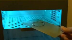
UV Radiometers (The “Puck”)
The most common tool for measuring UV on a flat conveyor is the disc-shaped radiometer, often called a “puck.” These devices are designed to be placed directly on the conveyor belt alongside the workpiece. As the puck passes under the UV lamps, it records the irradiance levels and calculates the total dose. High-end radiometers can measure multiple UV bands (UVA, UVB, UVC, and UVV) simultaneously, providing a spectral profile of the curing environment.
UV Mapping Radiometers
For more complex analysis, engineers use mapping radiometers. These devices don’t just provide a single peak number; they record data points at high frequencies (e.g., 2000 times per second) to create a visual graph of the UV intensity over time. This allows engineers to see exactly how each individual lamp in a multi-lamp system is performing and identify “dead spots” in the curing chamber.
UV Strips and Chemical Indicators
In cases where a bulky radiometer cannot fit—such as inside a narrow tube or on a highly contoured 3D part—engineers use UV-sensitive strips. These are thin, adhesive labels that change color based on the amount of UV energy they receive. While less precise than electronic radiometers, they are invaluable for verifying that UV light is reaching “hidden” areas of a complex workpiece. After exposure, the strips are analyzed using a spectrophotometer to correlate the color change to a specific mJ/cm² value.
Miniature Remote Sensors
For automated assembly lines where space is at a premium, engineers may use miniature sensors connected to a data logger via a thin cable or wireless link. These sensors can be mounted directly onto a jig or a prototype workpiece to measure energy in real-time during a production run.
The Step-by-Step Process of Measuring UV Energy
Measuring UV energy is not as simple as placing a sensor under a light. It requires a standardized protocol to ensure the data is repeatable and actionable.
Step 1: Calibration and Baseline Setting
Before any measurements are taken, engineers ensure their radiometers are calibrated to a NIST-traceable standard. Because UV sensors degrade over time due to high-intensity exposure, annual calibration is a requirement in most ISO-certified facilities. The engineer then establishes a “baseline” by measuring the system under ideal conditions with new lamps and clean reflectors.
Step 2: Sensor Placement
The sensor must be placed at the exact height of the workpiece’s critical surface. If the coating is on the top of a 2-inch tall component, the radiometer must be positioned 2 inches off the conveyor belt. Engineers often use custom-machined “nests” or blocks to hold the sensor at the correct orientation and height.
Step 3: Data Capture During a Production Run
The measurement is taken during an actual production cycle. This is crucial because the presence of other parts on the belt can sometimes cause reflections or shadows that affect the UV distribution. The radiometer travels through the entire curing tunnel, capturing the heat and light profile of the process.
Step 4: Analysis and Adjustment
Once the radiometer exits the chamber, the engineer analyzes the data. They look for the “Peak Irradiance” to ensure surface cure and the “Total Energy Density” to ensure through-cure. If the numbers are below the manufacturer’s specification for the coating, the engineer may increase lamp power, slow the conveyor speed, or adjust the lamp height.
Challenges in Measuring UV on 3D Workpieces
Measuring energy on a flat sheet of paper is straightforward, but industrial workpieces are rarely flat. Engineers curing automotive headlamps, medical catheters, or mobile phone housings face significant challenges.
On a 3D object, the UV light hits different surfaces at different angles. A vertical side-wall will receive much less irradiance than a horizontal top surface. To solve this, engineers often perform “profiling” using multiple sensors or UV strips placed at various points on a 3D model. This helps them identify “shadow zones”—areas where the geometry of the part blocks the UV light—allowing them to reposition lamps or add secondary “tack” lamps to ensure a 100% cure across the entire surface.
The Importance of Spectral Sensitivity
Not all UV light is the same. Traditional Mercury vapor lamps emit a broad spectrum of light, while UV LEDs emit a very narrow band (typically 365nm, 385nm, or 395nm). Engineers must ensure that their measurement tools are spectrally matched to their light source.
Using a radiometer designed for a Mercury lamp to measure a UV LED will result in wildly inaccurate readings. This is because the internal filters and photodiodes in the radiometer are calibrated to weight certain wavelengths differently. Modern engineers often use “LED-specific” radiometers that have a flat response across the specific peak of the LED to ensure the mW/cm² reading is a true reflection of the energy reaching the workpiece.
Thermal Management During Measurement
UV curing environments are notoriously hot. High-intensity lamps generate significant infrared (IR) energy, which can raise the temperature inside the chamber to over 100 degrees Celsius. Electronic radiometers are sensitive to heat; if the internal circuitry gets too hot, the readings can drift or the device can be permanently damaged.
Engineers mitigate this by using heat shields or by ensuring the radiometer is only exposed to the heat for the duration of the pass. Some advanced radiometers include internal temperature sensors that log the “internal temp” alongside the UV data, allowing the engineer to verify that the instrument stayed within its safe operating range during the measurement.
Statistical Process Control (SPC) and Documentation
In industries like medical device manufacturing or aerospace, measuring UV energy once a month isn’t enough. Engineers implement Statistical Process Control (SPC) by taking measurements at the start, middle, and end of every shift. This data is logged and graphed over time.
By tracking the gradual decline in UV irradiance, engineers can predict exactly when a lamp will fail or when a reflector needs cleaning. This “predictive maintenance” prevents scrap and ensures that every workpiece that leaves the line is cured to the exact same standard. It also provides a “paper trail” for quality audits, proving that the manufacturing process remained within the validated parameters.
Conclusion: From Art to Science
Measuring UV energy directly on a workpiece transforms UV curing from a “black box” process into a controlled, scientific operation. By moving beyond the lamp’s control panel and focusing on what the product actually experiences, engineers can optimize their lines for maximum speed, minimum energy consumption, and zero defects.
Whether using high-speed digital radiometers for flat-line production or chemical indicators for complex 3D geometries, the goal remains the same: ensuring the right amount of light reaches the right place at the right time. As UV technology continues to evolve—particularly with the rapid adoption of UV LED—the methods and tools for measurement will become even more critical in the quest for manufacturing excellence.
Visit www.blazeasia.com for more information.